- 3D Printer
UPS SERVICE
Shipping & ReturnsSTORES
Find retail locationsFREE SHIPPING
For orders above €100
CUSTOMER CARE
For All Your Questions
- Wireless & IOT
UPS SERVICE
Shipping & ReturnsSTORES
Find retail locationsFREE SHIPPING
For orders above €100
CUSTOMER CARE
For All Your Questions
- Sensors
UPS SERVICE
Shipping & ReturnsSTORES
Find retail locationsFREE SHIPPING
For orders above €100
CUSTOMER CARE
For All Your Questions
- Modules
UPS SERVICE
Shipping & ReturnsSTORES
Find retail locationsFREE SHIPPING
For orders above €100
CUSTOMER CARE
For All Your Questions
- Microcontroller Unit (MCU)
UPS SERVICE
Shipping & ReturnsSTORES
Find retail locationsFREE SHIPPING
For orders above €100
CUSTOMER CARE
For All Your Questions
- Development Boards
UPS SERVICE
Shipping & ReturnsSTORES
Find retail locationsFREE SHIPPING
For orders above €100
CUSTOMER CARE
For All Your Questions
Using a Brushless Motor as a Stepper Motor: Step 1 – Understanding BLDC Control Basics
Introduction
Motors play a crucial role in automation, robotics, and industrial control. Two commonly used types are Brushless DC (BLDC) motors and Stepper motors.
At first glance, these motors seem very different:
- Stepper motors are designed for precise angular movements but lose torque at high speeds.
- BLDC motors provide smooth, high-speed rotation but lack built-in position control.
However, with the right control strategy, a BLDC motor can be made to behave like a stepper motor, offering both precision and efficiency. Before achieving this, we need to understand the fundamental differences between these motors and the importance of control methods.
Understanding BLDC Motors
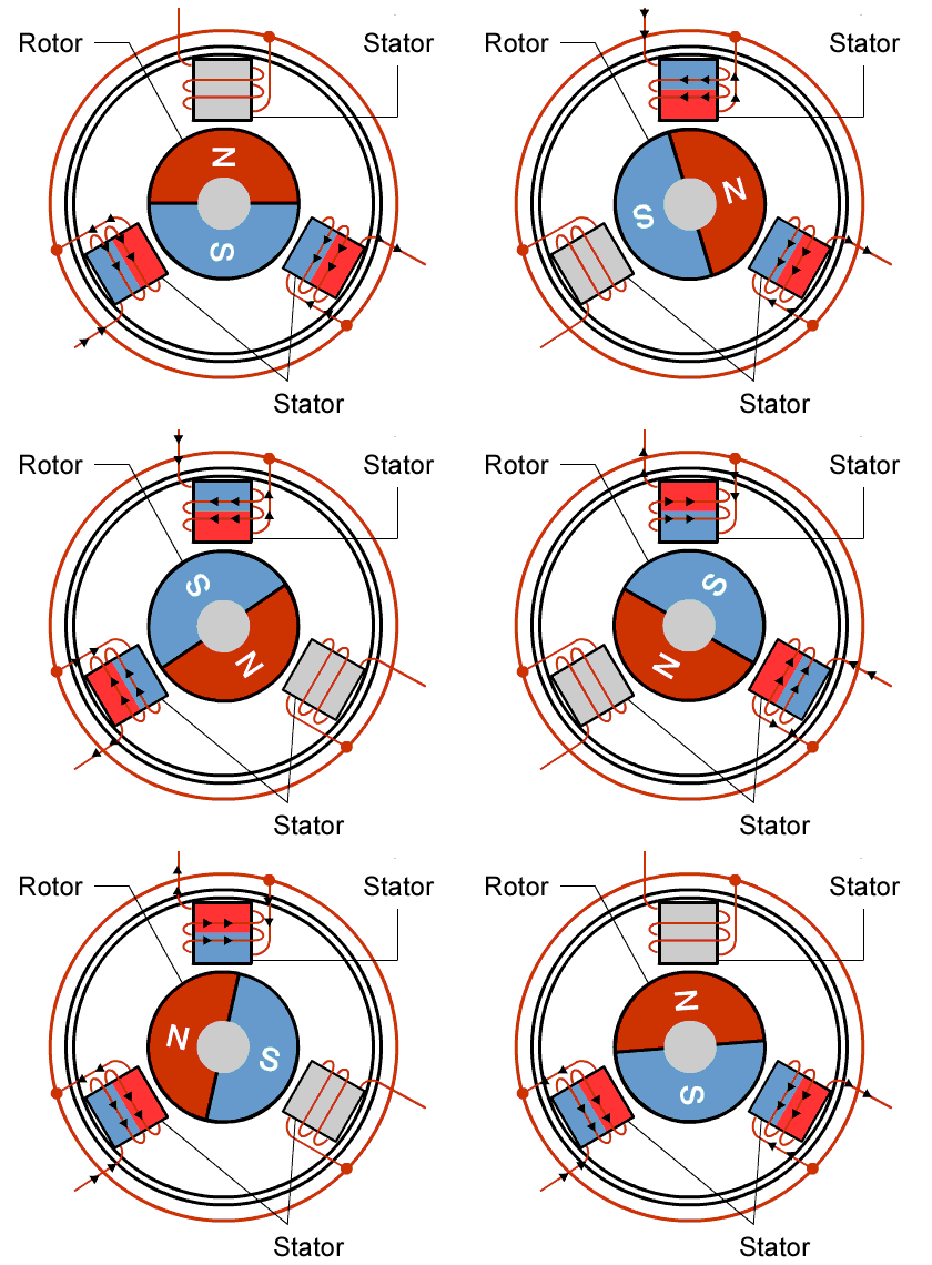
A BLDC motor is a highly efficient, electronically commutated motor that relies on:
- A Stator (Electromagnetic Coils): Generates a rotating magnetic field.
- A Rotor (Permanent Magnets): Follows the stator’s magnetic field, causing rotation.
- An Electronic Controller (ESC or Microcontroller): Determines when and how to energize the stator coils.
How a BLDC Motor Works
Instead of using physical brushes for commutation (like traditional DC motors), a BLDC motor relies on electronic switching:
- Controller energizes the coils in sequence → Generates a rotating magnetic field.
- Rotor (permanent magnet) follows this field → Produces smooth, continuous rotation.
- Sensors (like Hall effect sensors) or sensorless techniques (back EMF detection) are used to track rotor position.
Understanding Stepper Motors
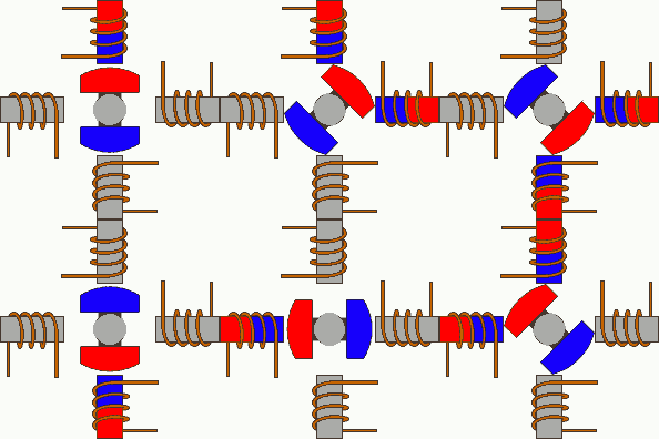
A Stepper motor is designed for precise position control, moving in fixed angular steps instead of continuous rotation. It consists of:
- A Stator with Multiple Electromagnetic Coils: Arranged in a circular pattern.
- A Rotor (Permanent Magnet or Iron Core): Aligns with the stator’s magnetic field.
- A Step Sequence Controller: Activates coils in a controlled order to rotate the rotor step by step.
How a Stepper Motor Works
Unlike BLDC motors, stepper motors do not rotate freely. Instead, they:
- Move in small fixed steps (e.g., 1.8° per step for a typical 200-step motor).
- Hold their position without feedback, thanks to magnetic detents.
- Follow a step sequence (Full Step, Half Step, or Microstepping) for control. Here is a animated image of a half stepping single-coil excitation stepper motor.
Key Differences Between BLDC and Stepper Motors
| Feature | BLDC Motor | Stepper Motor |
|---|---|---|
| Motion Type | Continuous rotation | Moves in discrete steps |
| Efficiency | High (only consumes power when needed) | Lower (constant power draw) |
| Torque at Speed | High at high speeds | Decreases significantly |
| Position Holding | Requires encoder feedback | Holds position naturally |
| Control Complexity | Requires electronic commutation (ESC) | Simple pulse-based control |
💡 Why Convert a BLDC Motor into a Stepper?
- Stepper motors lose torque at high speeds, while BLDC motors maintain performance.
- Stepper motors consume power even when stationary, whereas BLDC motors are more energy-efficient.
- Stepper motors vibrate due to discrete steps, while BLDC motors offer smoother motion.
👉 By implementing position feedback and closed-loop control, we can make a BLDC motor mimic a stepper motor, achieving both precision and efficiency.
Torque is the rotational force a motor generates. Higher torque means the motor can rotate heavier loads more easily. For gimbal applications, high torque and smooth motion are more important than speed.
Key BLDC Motor Specifications for Position Control
let’s define some important BLDC motor parameters:
1️⃣ Torque (Nm – Newton Meters)
Torque is the rotational force a motor generates. Higher torque means the motor can rotate heavier loads more easily. For gimbal applications, high torque and smooth motion are more important than speed.
2️⃣ KV Rating (RPM per Volt)
KV (Kilovolt rating) tells us how fast the motor spins per volt applied. A lower KV means: ✔ More torque.
✔ Slower, more controllable rotation (better for precision control).
✔ Ideal for gimbals and robotics.
Typical KV values:
- High KV (~1000 KV and above) → Fast rotation, low torque (used in drones, RC planes).
- Low KV (~100 KV – 500 KV) → High torque, slow rotation (good for precision control, robotics, gimbals).
3️⃣ Thrust (N – Newtons)
Thrust is mostly important for aerodynamic applications (like drones). For position control, we focus more on torque rather than thrust.
For this project, a low-KV motor (~100-300KV) with high torque is ideal, as it allows better precision when controlled with an encoder.
Understanding Open-Loop vs. Closed-Loop Control in Motors
When controlling an electric motor, there are two main strategies:
- Open-Loop Control (No Feedback)
- Closed-Loop Control (With Feedback)
These approaches determine how the motor responds to input signals and whether it can correct errors and maintain accuracy.
What Is Open-Loop Control?
🔹 Definition: Open-loop control is a system where the controller sends commands to the motor without checking whether the motor actually moves as expected.
How It Works
- The controller sends an electrical signal (e.g., PWM or step pulses) to the motor driver.
- The motor receives the signal and moves according to predefined rules.
- There is no feedback to verify if the movement was successful.
Example: Stepper Motor in Open-Loop Mode
- When you send 200 step pulses to a stepper motor, it moves exactly one full rotation (360°), assuming no mechanical issues.
- The system does not check if the motor actually moved or if it got stuck.
Advantages of Open-Loop Control
✔ Simple & Low Cost – No sensors or feedback systems are required.
✔ Predictable Motion – Works well if there are no disturbances (e.g., no load variations).
✔ Easy to Implement – Just send pulses, and the motor moves.
Disadvantages of Open-Loop Control
❌ No Error Correction – If the motor skips steps due to overload or resistance, the system won’t notice.
❌ Not Suitable for High Accuracy – External forces (e.g., friction, varying loads) can cause position errors.
❌ Limited Performance at High Speed – Stepper motors, for example, lose torque as speed increases.
What Is Closed-Loop Control?
🔹 Definition: Closed-loop control is a system where the controller receives real-time feedback from a sensor (like an encoder) to adjust the motor’s behavior dynamically.
How It Works
- The controller sends an initial signal to the motor.
- A sensor (e.g., an encoder) monitors the actual motor position or speed.
- The system compares the actual movement to the desired movement.
- If there is an error, the controller adjusts the input signal to correct it.
Example: BLDC Motor with Encoder in Closed-Loop Mode
- Suppose we command a BLDC motor to rotate exactly 90°.
- The encoder measures the actual movement.
- If the motor only moves 85°, the controller adjusts the signal to move the extra 5°.
- This ensures precise positioning, even if the motor faces resistance or load changes.
Advantages of Closed-Loop Control
✔ High Accuracy – Corrects position errors automatically.
✔ No Missed Steps – If the motor encounters resistance, it compensates.
✔ Works at High Speeds – Maintains performance even under load variations.
Disadvantages of Closed-Loop Control
❌ More Complex – Requires sensors (e.g., encoders) and a feedback control algorithm (e.g., PID).
❌ Higher Cost – Sensors and processing add cost compared to open-loop systems.
Why Does This Matter for Using a BLDC Motor as a Stepper?
A stepper motor naturally works in open-loop mode because it moves in predefined steps. However, a BLDC motor rotates continuously by default and does not have natural step movements.
To make a BLDC motor behave like a stepper motor, we must:
✅ Add an encoder to measure position.
✅ Implement closed-loop control to ensure precise positioning.
✅ Use a PID controller to fine-tune movement.
Without closed-loop control, a BLDC motor cannot precisely hold positions or move step-by-step.
Differences Between Open-Loop and Closed-Loop Control
| Feature | Open-Loop Control | Closed-Loop Control |
|---|---|---|
| Feedback | ❌ No Feedback | ✅ Uses Sensors |
| Accuracy | ❌ Can have errors | ✅ Adjusts errors dynamically |
| Cost | ✅ Low | ❌ Higher (requires sensors) |
| Best for? | Stepper Motors (when loads are predictable) | BLDC Motors (for precise control) |
For continuous rotation, BLDC motors work fine in open-loop mode.
For precise positioning (like a stepper motor), a BLDC motor must use closed-loop control.
Gimbal Control: Why Use BLDC Motors?
A gimbal stabilizes a camera by compensating for unwanted movements. It typically consists of:
- IMU (Inertial Measurement Unit): Detects motion and tilt.
- BLDC Motors: Adjust camera position based on IMU data.
- Microcontroller: Processes IMU data and sends signals to control motor movements.
Gimbals use closed-loop control to maintain stability:
- The IMU detects motion (e.g., tilt or shake).
- The controller calculates corrections.
- The BLDC motor moves in the opposite direction to compensate.
- This happens in real-time to ensure smooth stabilization.
Key Advantages of BLDC Motors for Gimbals:
- Smooth Motion – Unlike stepper motors, BLDC motors provide fluid movement without noticeable steps.
- Energy Efficiency – Uses only the necessary power, reducing heat and power consumption.
- Higher Torque at High Speeds – Essential for quick stabilization adjustments.
Next Steps
Now that we understand the basics, the next step is setting up a BLDC motor with a driver and testing basic rotation using PWM signals from an Arduino or ESP32. In the next post, we’ll cover:
✅ How to wire a BLDC motor to a controller
✅ How to send PWM signals for motor rotation
✅ Basic speed and direction control

