
Step 3: Adding an Encoder for Position Feedback
Introduction
Now that we’ve set up and tested the BLDC motor with an ESC, it’s time to add position feedback using an encoder. Without feedback, the motor only spins freely, but to make it behave like a stepper motor, we need precise control over its position.
This guide will cover:
✅ What an encoder is and why we need it.
✅ How to connect an encoder to the motor and read position data.
✅ A simple Arduino/ESP32 code to test encoder readings.
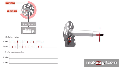
1. What Is an Encoder and Why Do We Need It?
An encoder is a sensor that tracks the position, speed, and direction of a rotating shaft.
🔹 Why is this important?
- Without an encoder, a BLDC motor just spins freely when powered.
- With an encoder, we can measure the exact angle and make the motor move like a stepper motor.
- Encoders enable closed-loop control, meaning we can correct errors in movement.
Types of Encoders
There are two main types:
1️⃣ Incremental Encoder
- Measures movement relative to its last position.
- Needs a reference point to determine an absolute position.
- Common for DIY projects due to lower cost.
2️⃣ Absolute Encoder
- Always knows the exact position, even after power loss.
- More expensive but better for precise control.
- Used in industrial robots and high-end gimbals.
For this project, an incremental encoder (e.g., AS5048A, AMT102-V, or optical encoders) will work fine.
2. Connecting the Encoder to the BLDC Motor and Microcontroller
🛠️ Required Components:
- BLDC Motor (from previous step)
- Incremental Encoder (e.g., AS5048A, AMT102-V)
- Arduino or ESP32
- Power Supply (5V for the encoder)
- 4 Signal Wires for Encoder Output
🔌 Wiring Diagram
| Encoder Pin | Connects To |
|---|---|
| VCC (5V) | 5V (Arduino/ESP32) |
| GND | GND (Arduino/ESP32) |
| A Output | Any digital pin with interrupt support |
| B Output | Any digital pin with interrupt support |
3. Reading Encoder Data with Arduino/ESP32
Let’s write a simple program to read the encoder position and display it on the Serial Monitor.
📝 Arduino Code for Reading Encoder Values
#define ENCODER_A Any digital pin number with interrupt support  // Encoder A signal connected to Any digital pin with  interrupt support
#define ENCODER_B Any digital pin number with interrupt support  // Encoder B signal connected to Any digital pin with  interrupt support

volatile int encoder_position = 0;

void encoder_ISR() {
  if (digitalRead(ENCODER_A) == digitalRead(ENCODER_B)) {
    encoder_position++;
  } else {
    encoder_position--;
  }
}

void setup() {
  Serial.begin(115200);
  pinMode(ENCODER_A, INPUT);
  pinMode(ENCODER_B, INPUT);
  attachInterrupt(digitalPinToInterrupt(ENCODER_A), encoder_ISR, CHANGE);
}

void loop() {
  Serial.print("Encoder Position: ");
  Serial.println(encoder_position);
  delay(100);
}
💡 Explanation of the Code
encoder_ISR()→ Interrupt function that updates the position based on encoder pulses.attachInterrupt()→ Monitors changes in the encoder signal and updates the position.Serial.print()→ Displays the current encoder position in the Serial Monitor.
👉 Open the Serial Monitor in the Arduino IDE to see the real-time position data.
4. Testing and Troubleshooting
✅ If Everything Works Correctly:
✔ The encoder count increases when the motor rotates in one direction.
✔ The encoder count decreases when the motor rotates in the opposite direction.
✔ You can see real-time position updates in the Serial Monitor.
❌ If Encoder Readings Are Incorrect:
❌ Encoder always shows zero?
- Check if the wiring is correct.
- Ensure the encoder power (5V) is properly connected.
❌ Encoder position jumps randomly?
- Make sure the wires are not loose.
- Use shielded cables to prevent electrical noise.
Next Steps: Step 4 – Implementing Closed-Loop Position Control
Now that we can read encoder values, the next step is to use this feedback to control the motor’s position using a PID controller.
In Step 4, we will:
✅ Explain what PID control is and why it’s important.
✅ Write a PID control loop to move the motor to specific angles.
✅ Fine-tune PID parameters for smooth and accurate motion.
Stay tuned for the next post! 🚀