
Step 4: Implementing Closed-Loop Position Control
Introduction
Now that we can read the encoder data, it’s time to implement closed-loop position control. This means using feedback from the encoder to control the motor’s movement precisely. Without this, the motor would just spin freely without knowing its exact position.
In this step, we will:
✅ Understand what PID control is and why we need it.
✅ Write code to control the BLDC motor’s position using PID.
✅ Tune the PID parameters for smooth movement.
✅ Test the system by commanding the motor to move to specific angles.
1. What is Closed-Loop Control?
A closed-loop control system is one in which the controller receives real-time feedback from a sensor (such as an encoder) to ensure the desired outcome is achieved.
In an open-loop system, the controller sends a command (e.g., “spin the motor”), but there is no feedback to check if the motor is actually reaching the correct position. If external forces affect the system, it won’t be able to correct itself.
In a closed-loop system, we use feedback (from the encoder) to compare the actual position to the desired position. If there is a difference between the two, the system adjusts the motor’s movement to correct any errors. This is essential for precise control and stability.
2. What is a PID Controller?
A PID controller (Proportional-Integral-Derivative) is a control system that continuously calculates the difference between a desired position (setpoint) and the actual position (feedback from the encoder). It then adjusts the motor’s output to correct this difference.
How Does PID Work?
The PID controller operates based on three components:
- Proportional (P): Reacts to the current error (difference between the target and actual position). If
Pis too high, the system may overshoot and oscillate. - Integral (I): Corrects past accumulated errors to eliminate steady-state errors. If
Iis too high, it may cause slow response or instability. - Derivative (D): Predicts future errors and applies damping to prevent overshooting. If
Dis too high, the system may respond too slowly.
The output of the PID controller is the sum of these three terms:
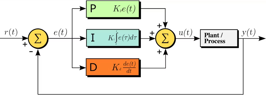
Output = (Kp * Error) + (Ki * Sum of Past Errors) + (Kd * Rate of Change of Error)The goal is to tune the PID values (Kp, Ki, Kd) to get a smooth and accurate movement with minimal overshoot or oscillation.
3. Writing the PID Control Code
Now, let’s write a program to move the motor to a specific position using PID control.
🛠️ Required Components:
- BLDC Motor + ESC (from previous steps)
- Incremental Encoder (e.g., AS5048A, AMT102-V)
- Arduino or ESP32
- Power Supply
🔌 Wiring Setup:
- BLDC Motor → ESC → PWM Control (Arduino/ESP32)
- Encoder A/B Outputs → Digital Pins (Arduino: 2 & 3, ESP32: GPIO16 & GPIO17)
📝 Arduino Code for PID Position Control
#include <PID_v1.h>

#define ENCODER_A Any Interrupt pin number // Encoder A signal connected to an Interrupt pin
#define ENCODER_B Any Interrupt pin number // Encoder B signal connected to an Interrupt pin
#define PWM_PIN Any PWM pin number // ESC PWM signal connected to a PWM pin

volatile int encoder_position = 0;
double setpoint = 0, input = 0, output = 0;

// PID Parameters (Tune these for best performance)
double Kp = 2.0;   // Proportional Gain
double Ki = 0.5;   // Integral Gain
double Kd = 0.1;   // Derivative Gain

PID myPID(&input, &output, &setpoint, Kp, Ki, Kd, DIRECT);

void encoder_ISR() {
  if (digitalRead(ENCODER_A) == digitalRead(ENCODER_B)) {
    encoder_position++;
  } else {
    encoder_position--;
  }
}

void setup() {
  Serial.begin(115200);
  pinMode(ENCODER_A, INPUT);
  pinMode(ENCODER_B, INPUT);
  pinMode(PWM_PIN, OUTPUT);
  attachInterrupt(digitalPinToInterrupt(ENCODER_A), encoder_ISR, CHANGE);
  myPID.SetMode(AUTOMATIC);
  myPID.SetOutputLimits(1000, 2000); // Adjust PWM range for ESC
}

void loop() {
  input = encoder_position;
  myPID.Compute();
  int pwm_signal = (int)output;
  analogWrite(PWM_PIN, pwm_signal);

  Serial.print("Target: "); Serial.print(setpoint);
  Serial.print(" | Position: "); Serial.print(encoder_position);
  Serial.print(" | PWM: "); Serial.println(pwm_signal);

  delay(50);
}
What is PID Tuning?
Tuning refers to adjusting the Kp, Ki, and Kd values to achieve the best performance. If the values are incorrect, the motor may:
- Oscillate around the target position.
- Respond too slowly or overshoot the target.
- Fail to correct steady-state errors.
🔧 Auto-Tuning with Arduino Library (Optional)
Instead of tuning manually, you can use the PID Auto-Tune Library to find the best values automatically.
4. Testing the PID Control
✅ How to Test:
1️⃣ Upload the code to the Arduino/ESP32.
2️⃣ Open the Serial Monitor and observe the encoder position.
3️⃣ Set different target positions by modifying setpoint.
4️⃣ Watch the motor move to the exact position and hold there.
❌ Troubleshooting:
❌ Motor oscillates too much? → Reduce Kp, increase Kd.
❌ Motor moves too slow? → Increase Kp and Ki.
❌ Motor overshoots the target? → Adjust Kd to add damping.
5. Fine-Tuning the PID Parameters
For best results, you need to experiment with the PID values:
🔧 Manual PID Tuning Method:
1️⃣ Start with Kp = 1.0, Ki = 0, Kd = 0.
2️⃣ Increase Kp until the motor reaches the position but oscillates.
3️⃣ Increase Kd until oscillations stop.
4️⃣ Increase Ki slowly to remove steady-state errors.
🔧 Auto-Tuning with Arduino Library (Optional)
Instead of tuning manually, you can use the PID Auto-Tune Library to find the best values automatically.
6. Next Steps: Simulating Stepper Motor Behavior (Step 5)
Now that the motor can move to specific positions, the next step is to simulate a stepper motor by controlling it with step signals and directional movement.
In Step 5, we will:
✅ Modify the code to accept step pulses like a stepper motor.
✅ Implement directional control for precise movements.
✅ Test the system with a G-code sender or external controller.
Stay tuned for the next post! 🚀